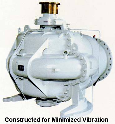
Vibration and Out-of-balance Equipment
When spinning equipment is out of balance. Vibration from out-of-balance rotating equipment can be frightening. The ground shakes, machines jump about, hold down bolts come loose and parts break. An unbalanced rotating body will produce forces on its bearings and transmit them throughout its structure and into the foundations.
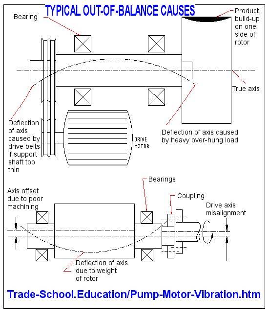
CAUSES OF OUT-OF-BALANCE
Below list some common causes for unbalance.
Bent or bowed between support bearings
Overhung weight bends shaft under gravity
Unevenly distributed solid or liquid inside rotor
Loose parts on the rotor
Eccentrically manufactured diameters on the rotor
Misalignment of the drive train to the rotor axis
Loose drive couplings flop about
Loose tolerances between assembled parts on rotor
Shoulders on rotor manufactured out-of-square to axis
Voids or cavities within the rotor
Misalignment of bearings force shaft to bow
The drawings below provide examples of some of the problems listed in the table above.
REDUCING OUT-OF-BALANCE PROBLEMS
Minimizing vibration involves minimizing out-of-balance forces. The following table indicates simple actions to take to reduce the problems of out-of-balance.
Make the rotor with all diameters on the same axis
Machine the rotor from one piece of material
Machine the rotor complete without altering the initial machining set-up
Finish machine multiple part rotors when fully assembled on the shaft
Reduce lengths of unsupported sections and overhangs
Keep tolerances tight on parts assembled on the rotor
Align the drive train to the axis of the rotor carefully
Ensure the bearing supports are aligned
BALANCING ROTORS
An out-of -balance machine can be made to run smoothly by balancing the rotating parts to within acceptable limits. Balancing is the process of attempting to improve the distribution of mass in a body so that it rotates in its bearings without unbalanced centrifugal forces. It can only be attained to a certain degree.
When a part is to be balanced it is necessary to specify the quality of balance required. The more precise the balance required the higher the cost to attain it. Relevant standards have been set for various types of components. The list below is taken from BS 6861 and shows typical grades of balance for common components.
| Balance Quality | Rotor Types – General Examples |
|---|---|
| G4000 | Drive trains of slow marine diesel engines |
| G1600 | Drive trains of rigidly mounted large two-cycle engines |
| G630 | Drive trains of large four-cycle engines |
| G250 | Drive trains of fast, rigidly mounted diesel engines |
| G100 | Complete assembled engines of cars, trucks and locomotives |
| G40 | Car wheels, wheel rims, wheel sets, drive shafts |
| G16 | Propeller shafts, individual car engine components, crushing machine parts |
| G6.3 | Fans, pump impellers, electric motors, general machinery parts |
| G2.5 | Gas and steam turbines, computer disks, machine tool drives |
| G1 | Grinding machine drives, tape recorder drives |
| G0.4 | Precision grinder spindles, gyroscopes |
Attaching or removing weight at relevant points on the rotor permits balance corrections. For example specifically weighted tags can be welded to the rotor, or metal can be removed by drilling holes into the rotor at relevant positions.
To minimize the possibility of vibration problems, specify to the machine shop the degree of balance quality required of the part. To improve the accuracy of balancing send all the attached assemblies such as couplings, bolts, keys and pulleys with the rotor so the effect of the components can be allowed for in the balance corrections.
Vibration and its control
Vibration in equipment is the result of unbalanced forces. Out-of-balance is corrected by adding or removing material so that when the equipment is operating the unbalance is controlled to an acceptable level.
The transference of unbalanced forces through equipment into neighboring structures causing them to shake is vibration. The motion of a body is limited by what connects it to a machine and the walls in which it moves. Every time there is a change of direction unbalanced forces produce a shock. This shock travels throughout the machine and is transmitted to all connected items.
Mostly a spring is used to isolate vibration movement or a damper is used to absorb the movement. A full explanation of vibration control requires calculus and is beyond the scope of this article. The spring-mass-damper system of Figure No. 1 below is a simplified representation of a vibration control system.
Spring force and damper pressure control the mass’ movement. The damper piston moves and so absorbs the vibration. Where as the spring flexes and isolates the movement from its attachment.
The rate of vibration is called the frequency. It is measured in cycles per second and has the units Hertz. A four-pole electric motor rotates at about 1500 RPM. This is 25 cycles per second or 25 Hertz. Vibration caused by an external applied force is known as a forced vibration because the mass oscillates at the frequency of the external force. An example is the shake produced by the moving pistons and crankshaft in a car engine.
The equation for the natural frequency of an undamped spring-mass system moving in one direction is
fn = ½ p Ö(K/M)
Where K is the spring stiffness and M the mass.
This equation lets us find the resonance frequency for a mass–spring system. Such a system can be represented in the drawing above by removing the damper.
Wild gyrations develop when the forced frequency nears the system natural frequency. Every system has a natural frequency and will shake to destruction if it is forced to move at that rate. This phenomenon is known as resonance. An example would be the shattered wineglass caused by an opera singer’s voice or vibrations in long, thin shafts that start and then stop as the shaft speed goes through its natural frequency speed.
The four methods of vibration control are listed below.
| Reduce or eliminate the exciting force by balance or removal |
| Use sufficient damping to limit amplitude |
| Isolate the vibration source from the surrounds by using spring mounts of appropriate stiffness |
| Introduce a counterbalancing force opposite in phase to the exciting force |
Most importantly every moving mass must be balanced about its center of rotation. The topic of rotary machine balancing was introduced at the beginning of this article. (Also it can be found in the eBook “Rotating Machinery Long Life Basics”.) The article indicated that rotating masses must be balanced to an acceptable standard. Out–of-balance rotors cause vibration because the center of mass of the rotor is eccentric (not running true) to its center of rotation. The spinning off-center mass is continually being flung outward. The machine’s bearings hold the mass in place and react against the developed forces. Vibration results as first the mass is on one side of the bearings and then it is on the other. Balancing aims to distribute the mass evenly about the running center. Figure No. 2 shows eccentricity between the center of mass and the center of rotation.
Materials such as rubber dampen shaking. The rubber flexes and absorbs the movement within itself. The sketch below is of a simple rubber vibration damper. Because rubber cannot compress much to accommodate movement, rubber dampers are normally used for low amplitude, high frequency vibration where noise transference is a problem. Shock absorbers are used for large amplitude, low frequency situations where springs alone would produce bouncing. An example is in car suspensions as shown in Figure No. 3.
The natural frequency can be moved away from the forcing frequency by changing the weight of the system. Making the frame of a vibrating machine heavier will lower the assembly’s natural frequency. Concrete added to the base frames of lightweight fans reduce vibration by lowering the natural frequency and moving it away from the forcing frequency produced by the rotating blades.
A vibrating mass can also be isolated from its surroundings by springs. The springs deflect under the shaking body. Installing isolation springs make the spring’s natural frequency the governing frequency for vibration transfer. Altering the spring stiffness allows us to select the desired amount of isolation.
Spring stiffness controls the amount of vibration transferred to the attachment. Too stiff will transmit vibration, while insufficient stiffness will cause bounce. The correct spring stiffness can be found using charts available from specialist vibration control companies. The isolation springs must not have a natural frequency near the forcing frequency of the isolated equipment. In such a case the system would start to resonate and jump about. Figure No. 4 below shows an air compressor supported on springs. Stiffer springs are at the heavier end of the machine to both keep the machine level and to prevent resonance developing as the mass increases. The drawing also indicates that vibration is usually in more than one direction
An out-of-phase mass is a method not often used to control vibration. It is possible to use a weight with an opposite vibration pattern to negate the out-of-balance forces. This method has been used in motor car engines where a shaft with an eccentric mass is spun in the opposite direction to the crankshaft.